Building a smart mirror with Home Assistant
Have you ever dreamed of having a futuristic smart mirror that can display information while you get ready in the morning? Well, dream no more! For the past two months, I’ve been busy working on my latest project, a smart magic mirror that brings the future to your home. With this mirror, you can catch up on the news, check the weather, and even receive personalized messages —all while admiring your reflection. In this blog post, I’ll take you through my journey of building this innovative gadget and share some of the challenges and lessons I learned along the way.
Hardware
- Raspberry Pi Pico
- 3 1.3” SPI/I2C SH1106 Oled displays
- Adafruit TSL2591 Light Sensor
- 20 cm X 30 cm One-way mirror
- IKEA RIBBA 21x30
For this project, I utilized the Raspberry Pi Pico microcontroller from the Raspberry Pi Foundation. This compact, energy-efficient computer is ideal for IoT-based projects due to its Wi-Fi connectivity and low power consumption. With a plethora of GPIO pins available for device and sensor control, I opted to pair the Raspberry Pi Pico with three 1.3” OLED displays. I integrated these displays into an IKEA RIBBA frame with a one-way mirror, which conceals the electronics while allowing the displays to shine through from behind. The brightness of the displays is regulated by a light sensor sitting behind the mirror as well. The resulting effect is a stunning, futuristic display that combines cutting-edge technology with sleek design.
Software
- ESPHome
My main goal was to display information directly from Home Assistant. Information such as the current temperature inside my room, electricity price and time are things I look up multiple times each day, then why not embed them in a smart display?
ESPHome is a really cool piece of software from Nabu Casa. It is mainly an add-on to Home Assistant which lets you configure a microcontroller by writing YAML code. The add-on interprets the YAML file and then compiles a program that is flashed to the microcontroller wirelessly over wifi.
How to configure I2C SH1106 display
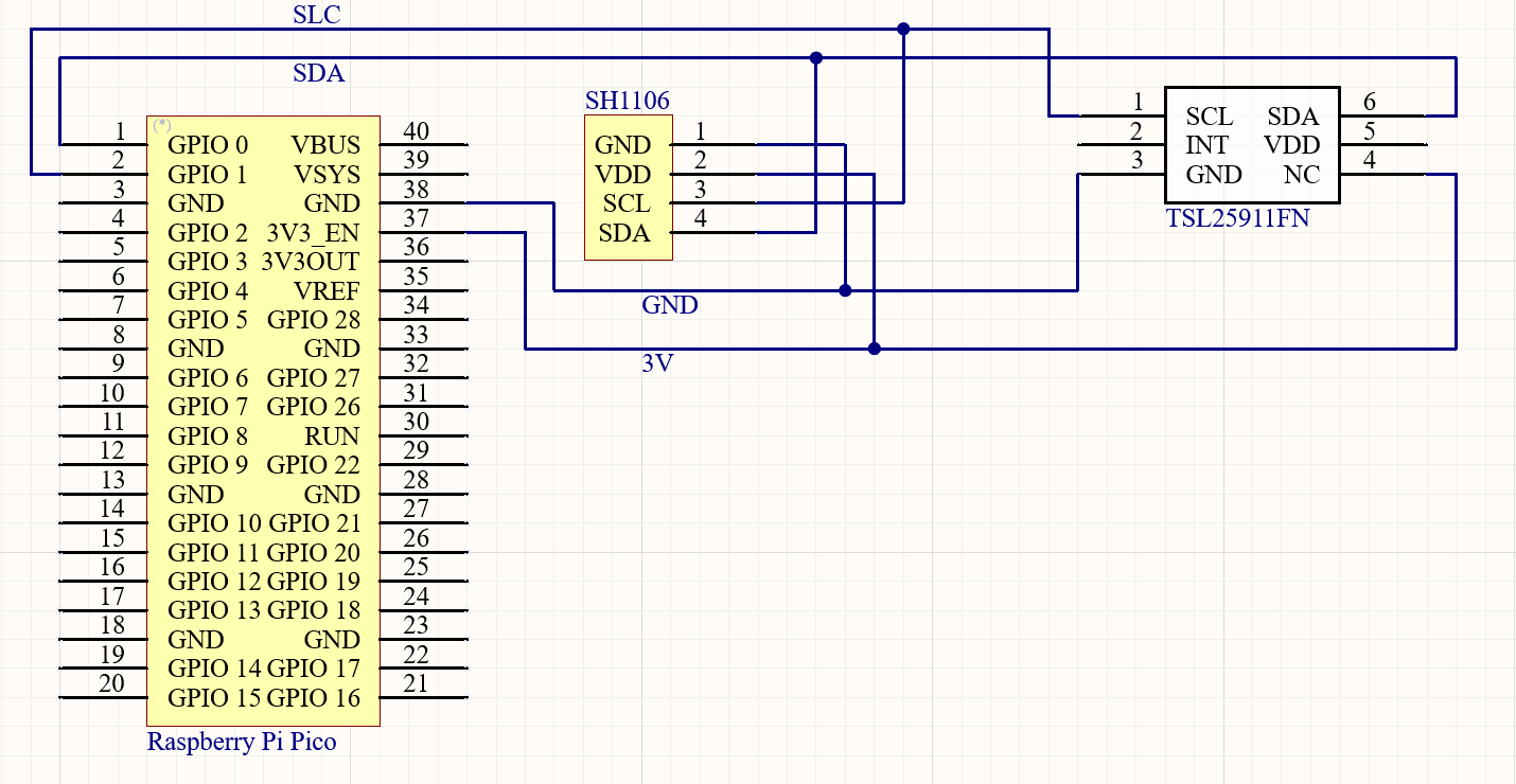
First we need to define which GPIO pins will act as the SDA and SCL for I2C communication.
i2c:
  - id: bus1
    sda: GPIO00
    scl: GPIO01
    scan: True
Now we can tell ESPHome how our display should be set up.
display:
  - platform: ssd1306_i2c
    update_interval: 1h
    model: SH1106_128X64
    address: 0x3C
    id: my_display1
    flip_x: false
    flip_y: false
    lambda: |-
      it.printf(1, 25 * (rand()%10)/10, id(roboto), "%.2f kr/kwh", id(electricity_price).state);
To be able to find the device we need to specify its I2C hardware address, in this case its 0x3C. I then set the update interval to be an hour since the electricity price doesn’t change more often than that either way. We can display information on the display by using the printf function. The functioning principle bears similarity to that of C/C++. Initially, the X position value is assigned a value of 1px, while the Y value is determined as 25 times a random number within the range of 0-1. Given that oled displays are prone to long-term burn-in, the specification of distinct Y positions is necessary to mitigate the occurrence of repetitive pixel illumination. A font is then specified followed by how the text is to be formatted. %.2f simply prints a float value rounded to two decimals.
On the two remaining displays, I displayed the current temperature in my room and the current time. Let’s declare a time block in ESPHome.
time:
  - platform: homeassistant
    id: homeassistant_time
Now we can use the time wherever we’d like. So like before, let’s use a printf function.
it.strftime(15, 25 * (rand()%10)/10, id(robotoBig), "%H:%M", id(homeassistant_time).now());To display the room temperature, let’s define the sensor and then use it.
sensor:
  - platform: homeassistant
    entity_id: sensor.bedroom_sensor_temperature
    id: room_temp
    internal: true
it.printf(10, 25 * (rand()%10)/10, id(robotoBig), "%.1f C", id(room_temp).state);How to configure I2C TSL2591
Seeing as we’ve already specified how I2C data and clock are used, be don’t need to do that again. This time we only need to configure the light sensor.
- platform: tsl2591
    id: "my_tls2591"
    address: 0x29
    update_interval: 2min
    i2c_id: bus1
    gain: MEDIUM
    power_save_mode: False
    integration_time: 100ms
    visible:
      name: "TSL2591 visible light"
    infrared:
      name: "TSL2591 infrared light"
    full_spectrum:
      name: "TSL2591 full spectrum light"
    calculated_lux:
      id: i_lux
      name: "TSL2591 Lux"
    actual_gain:
      id: "actual_gain"
      name: "TSL2591 actual gain"
At first glance, it might seem like a lot is happening but in reality, it’s pretty simple. There mainly two important settings to be considered, address and gain.
I randomly tried setting the gain to MEDIUM and to my surprise it worked pretty well.
The gain on a TSL2591 is a feature that controls the sensitivity of the sensor to the incoming light. Specifically, it amplifies the signal that is detected by the photodiodes in the sensor. Therefore it’s important to choose a fitting gain to not over- or under-expose the sensor.
The address field is set to 0x29 since that is the hardware address. It is important for it to not have the same address as any other device since all I2C devices communicate through a shared physical medium.
To regulate the brightness of the displays, I employed a method that involved utilizing the LUX light value read from the sensor to adjust the brightness level of the displays accordingly.
if(lux > 0.3 && lux < 2){
id(my_display1).set_contrast(0.5);
id(my_display2).set_contrast(0.5);
id(my_display3).set_contrast(0.5);
} else {
id(my_display1).set_contrast(1.0);
id(my_display2).set_contrast(1.0);
id(my_display3).set_contrast(1.0);
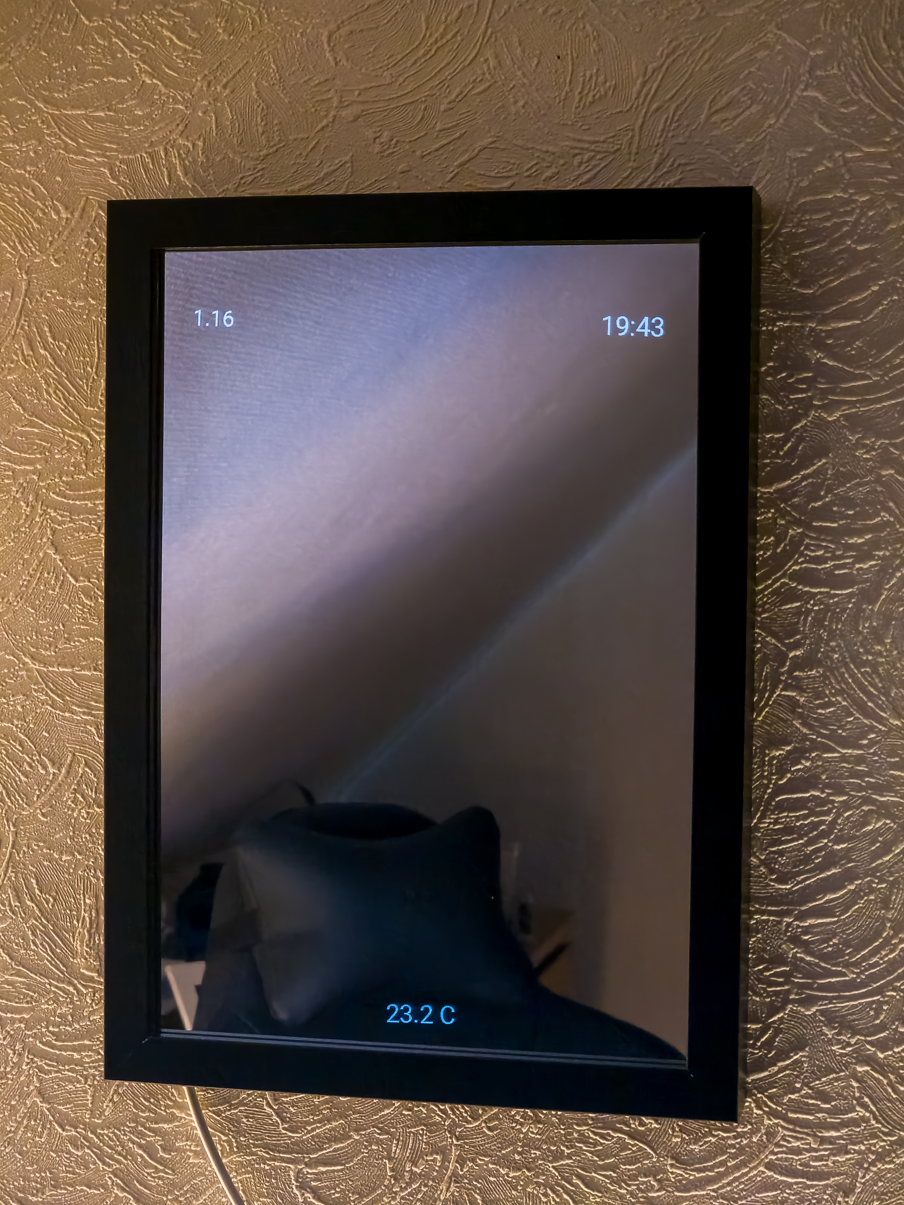
}Final result
Here’s a picture showcasing the final result, I am really happy with out it turned out.